Programming
First things first, the data which I am going to record will be of a high frequency (around 38KHz), and the attiny44 has only 256 SRAM bytes. Which means if I am storing data as integer, I would have a miximum of:
integer - 16 bits
16 bits = 2 bytes :O
256/2 = 128
But as all of my data will consist of 1s and 0s (on and off), i can make use of the other 15 bits that I would not be using if In going to store each on and off in a single integer by storing them as bits, which gives me 16 times more space. This
tutorial was helpful for this stage.
Programmer bash file
I have created a bash file that makes reprogramming the microcontoller easier. This bash file reprograms the microcontroller just by running "bash Program", where Program stands for the file name of the bash file. The code inside the file is shown below:
#!/bin/bash

avr-gcc -w -Os -DF_CPU=2000000UL -mmcu=attiny44 -c -o main.o main.c
avr-gcc -w -mmcu=attiny44 main.o -o main
avr-objcopy -O ihex -R .eeprom main main.hex
avrdude -F -p t44 -P usb -c avrisp2 -U flash:w:main.hex
avrdude -F -p t44 -P usb -c avrisp2 -U lfuse:w:0x7E:m
Code
Here is how I have designed the code:
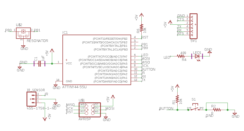
Declaring inputs and outputs
DDRA = 0b10000000;
S = PINA & 1<<PA3; Push button
V = PINA & 1<<PA2; IR signal
Clearing the array for a new signal
for ( i = 0; i < 94; i++ ){
A[i] = 0;
}
Saving the new signal
if (V < 1){
Trigger, if there is a signal from the sensor, the recording starts.
for(i = 0;i<1520;i++){
index for the number of bits to be recorded.
V = PINA & 1<<PA2;
Checks the voltage across the pin.
if (V < 1){
PORTA |= 0b10000000;
if yes, the LED goes on
index = i/16;
index for the array (A[index])
pos = i%16;
The position of the bit (remainder by division)
flag = 1;
flag = flag << pos;
Marks the position of the bit, by shifting. eg: ..000010000...
A[index] = A[index] | flag;
Adds the bit to the element in the array. eg: ..000100100...|..000010000...=..000110100...
_delay_us(658);
}
else{
PORTA &= ~(0b10000000);
if not, the LED turns off
index = i/16;
pos = i%16;
flag = 1;
flag = flag << pos;
flag = ~flag;
A[index] = A[index] & flag;
just to make sure, the bit is removed.eg: ..000110100...&..111101111...=..000100100...
_delay_us(658);
}
}
_delay_ms(5000);
delay to give an indication to the user to stop
}
Sending the recorded signal
if (S < 1){
if the button is pressed
for(i = 0;i<1520;i++){
index = i/16;
pos = i%16;
flag = 1;
flag = flag << pos;
flag = ~flag;
if ( ~(A[index] | flag) == 0 ){
eg: A[index]=...1010...,flag=...1101...
...1010...|...1101...=...1111...
~(...1111...)=0 (hence yes)
PORTA |= 0b10000000;
_delay_us(658);
}
else{
PORTA &= ~(0b10000000);
_delay_us(658);
}
}
}
The whole code
#include <avr/io.h>
#include <util/delay.h>
#include <avr/pgmspace.h>
#define F_CPU 20000000UL

//http://www.mathcs.emory.edu/~cheung/Courses/255/Syllabus/1-C-intro/bit-array.html

int main(void)
{
	DDRA = 0b10000000;
	int S;
	double V;
	int A[94];
	int f;
	int pos;
	unsigned int flag;
	unsigned int i = 0;


	while(1){
		S = PINA & 1<<PA3;
		V = PINA & 1<<PA2;
		double time = 0.02632;
		int index = 0;

		if (V < 1){
			for ( i = 0; i < 94; i++ ){
				A[i] = 0;
			}
			for(i = 0;i<1520;i++){
				V = PINA & 1<<PA2;
				if (V < 1){
					PORTA |= 0b10000000;
      		index = i/16;
      		pos = i%16;
					flag = 1;
	    		flag = flag << pos;
	      	A[index] = A[index] | flag;
					_delay_us(658);
				}
				else{
					PORTA &= ~(0b10000000);
       		index = i/16;
       		pos = i%16;
      		flag = 1;
      		flag = flag << pos;
					flag = ~flag;
      		A[index] = A[index] & flag;
					_delay_us(658);
				}
			}
			_delay_ms(5000);
		}

		PORTA &= ~(0b10000000);


		if (S < 1){
			for(i = 0;i<1520;i++){
				index = i/16;
				pos = i%16;
				flag = 1;
				flag = flag << pos;
				flag = ~flag;
				if ( ~(A[index] | flag) == 0 ){
					PORTA |= 0b10000000;
					_delay_us(658);
				}
				else{
					PORTA &= ~(0b10000000);
					_delay_us(658);
				}
			}
		}
		PORTA &= ~(0b10000000);
	}
}